I will be adding to this page over time as I get to the still photo's and other information about my new antenna.
This antenna was conceived and designed by Doug Waller NX4D hence the name of the antenna the Waller Flag. Doug
first designed and built his antenna in a vertical position on a short tower at his QTH in Florida.
Over the last few years they have learned that there advantages and disadvantages to
having either a Vertical Waller Flag or a Horizontal Waller Flag if you have some reasonable height to put it up on a tower.
Carlos N4IS has both at his QTH. Another slight variation is the one that Pete N8PR now SK had where it is an up in the air on a tower but also has the ability
to rotate the Boom meaning he can change polarization of the antenna from Horizontal to Vertical or do 45 degrees
either side of Horizontal. In some cases it can be better tilted one way or the other.
I chose the Horizontal Waller Flag over the vertical version. Reasoning was that #1 I had a nice tower height for the antenna.
#2 as long as the antenna is horizontally polarized you don't have to Neutralize your Towers. I did eventually Neutralize all three towers.
That made a considerable difference in my 4 square transmit/receive array for 160M. It noticably increased the F/B and F/S pattern of the array.
Think here diviersity receive. The Horizontal Waller Flag and the Vertical 4 square array.
Since installing this HWF antenna I have added 7 new Countries to my 160M DXCC total is now 323.
Only 27 countries left in the World that I don't have a 2 way contact with.
Here I will ad that after watching and ground assisted as one of these
Horizontal Waller Flag antennas was put up at Doc N4WW's QTH in Florida this last spring where Dennis his climber assembled this antenna up
on top of one of Doc's towers I decided there was no way I was going to try to do that on the top of my tower.
Too many other antennas above and below it to try fighting a 44 foot boom and assembling this antenna up there.
Maybe a couple young guys could do it but unfortunately I don't have those available so it was
HIRE A CRANE to do the JOB.
Enter the Don R. Fruchey Inc Crane and equipment company
Yes I have used this company for other Crane / Tower projects prior to this project.
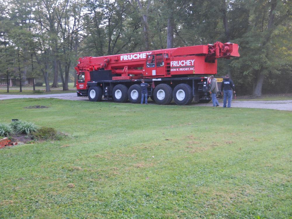
They have the right equipment to do your job. They also have a really great bunch of guys in their Crane Crews.
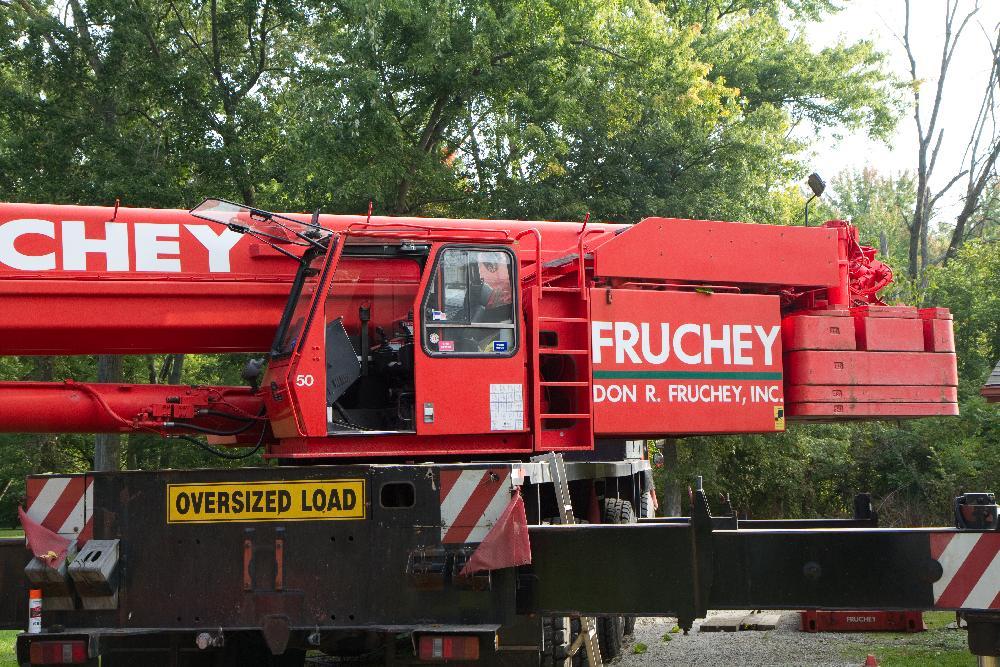
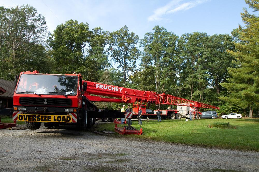
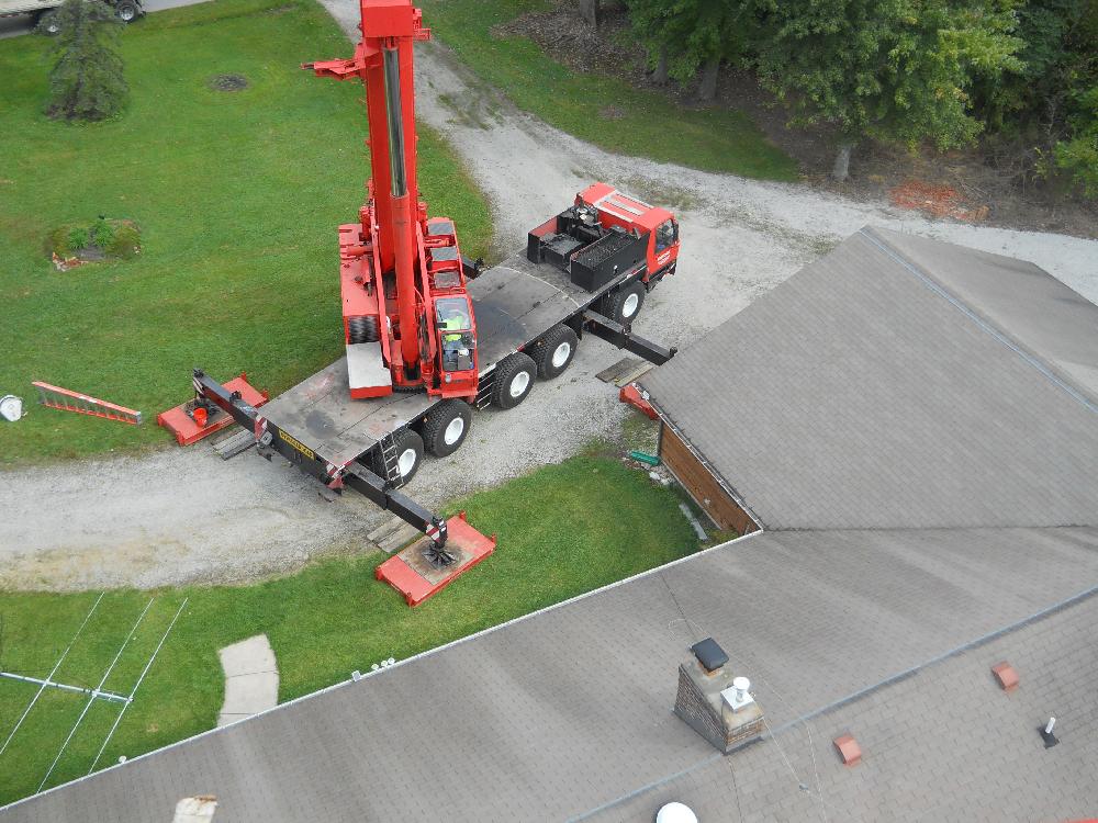
And the above crane is what was chosen for this project. This crane is capable of 295 foot total height. For this job it was to be setup to
do 212 feet height. This is due to position of the crane in front of our house. This kept the crane for the most part on the driveways rather than taking it into the backyard
where once in the past we managed to get a considerably smaller crane stuck and had to call out a pair of those big Semi-Wreckers to get the crane out of the yard.
This puts the crane about 120 feet away from the tall tower. I also had some maintenance work to do on the other two towers. And setup as this one was we could reach all three towers
and to the needed work from the same position of the crane. So at first it was 130 feet out and 150 foot level needed for the work plus the amount of cable and space
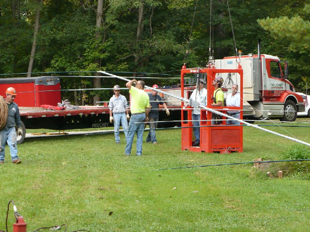
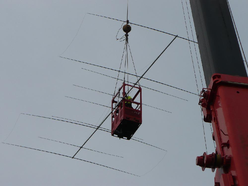
for the "ManCage" so all work was performed from the ManCage on this the Crane Day at K9UWA QTH.
Yes that is ME K9UWA in the mancage along with Kevin one of Fruchey's ironworkers part of the crane crew.
A Great big Thanks to the Don Fruchey Crew
So as they say .. ON WITH THE SHOW.
If you haven't already seen it this is the link to the You Tube Video of the Crane Day Antenna project at K9UWA
then at this point take about 8 minutes and watch the Video or this project.
https://www.youtube.com/watch?v=WXvRrummVFY&feature=em-share_video_user
Credit for the Video and some of the pictures to Dino Raptis KR9V
Dino with the Quad Copter with Camera and his GoPro Headband camera stuck on my head as I
am the guy up in the "Mancage" doing the work along with one of the Fruchey Crewmembers.
Dino of course doing all the editing and posting of the YouTube Video. I wouldn't know where to begin!
Still Photo's on down the page are credited to:
Charlie Hall KC9LA
Gary Nichols KD9SV
Dino Raptis KR9V
Big Thanks Guys for the assistance on the project as well as all the fine pictures.
I have been asked some questions and did my best to answer them. However the below pictures will
probably answer some more of the questions.
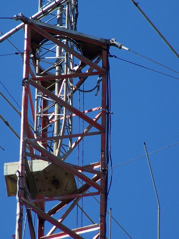
First someone asked about how the Rotary Rohn 45g mast was built and rotates.
The whole works sets on top of a Telrex Rotor. It is positioned 7 feet down from the top of the main tower.
The shiney ring you see at the top of the main tower is a 4 inch wide band of stainless steel rolled into a
near perfect circle. On the legs of the tower are 4 per leg bearings that run almost against that stainless steel ring.
The tower was put up by me and a crane in 1988
Tower was built by Tower Communications Inc. It was a 225 footer and the deal was negotiated by my long time old friend
Jack Shutt W9GT who worked at the time for GTE. The tower was down on the ground in Logansport, IN as it
had been replaced by I think it was a 320 footer by GTE. Jack got 80 feet of the tower and still of course has it up
at his QTH. and I have the other 140 feet of it. Jack obtained this tower in 1976 and Jack and I put up his 80 feet
in 1977. I put up the 140 foot after purchasing this QTH from Lamar Ray W9LT in 1988.
Top of the tower with Telrex Rotor
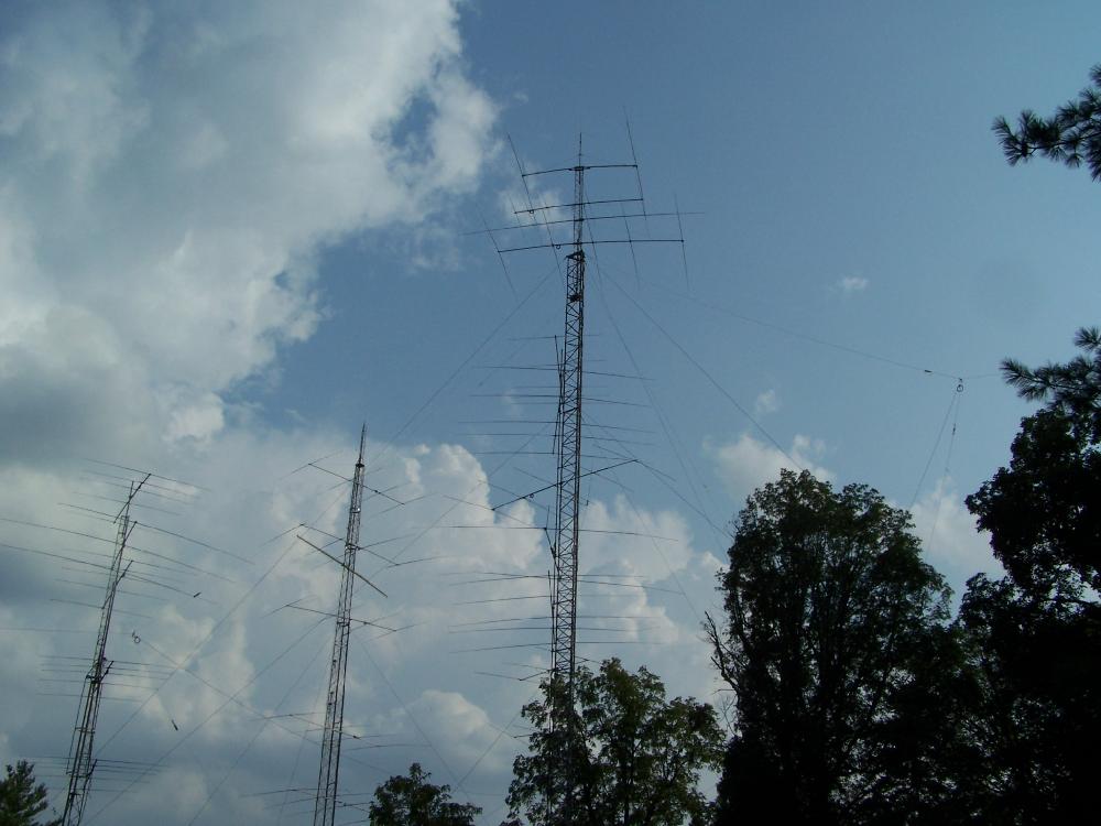
This is a the Tower and antennas as they existed prior to installing the Horizontal Waller Flag antenna
Ignore the rear two towers. We are talking about the top of the tallest tower.
Top yagi is 2 element Cushcraft 40M
Next antenna down is a 5 element 10M HyGain 105bas It will be removed and replaced by the new dual purpose
Horizontal Waller Flag plus the 5 element 10M HiGain elements interlaced on the 44 foot boom.
If you look coming from the top of the tower down and to the right you see a wire antenna. That is one of 4 identical antennas that
are together the phased 4 square transmit array for 160M. It is similar to what is known as the K8UR method of building a 4 square phased array.
It is switched and controlled by a Comtek 4 square modified box. I guess since I presently have 321 entities on 160M that it must work well.
I only need 29 more to have all the countries of the World on this the 160M Amateur Band. Currently there are only 22 stations in the World who are
ahead of me on this very difficult to operate 160m Amateur Radio Band.
Consider the following. In order for us Hams to make a two way contact with another country we need the following to happen.
First both stations need have to be Dark as in night time as during daytime propagation on this band is limited to maybe a few hundred miles. Where at
nite the signals can travel anyplace where you have a nite to nite path. So at the absolute farthest place on Earth from this location there will be one nite where
you do have a nite to nite path that Might be available. Next has to do with sunspot activity and general radio propagation. Sunspot activity is for the most part
an Eleven Year top to top or bottom to bottom cycle. The Tops and Bottoms can and have had considerable differences in sunspot and sun storm activity.
I have been at this project since 1971 so I have been through some good eleven year cycles and through a few bad cycles. In order to make the really Long Haul
contacts to the farthest places on Earth you need to also have the right time of the cycle .. a nite to nite path... and next both stations need to be there with effective transmitting
and receiving equipment and antennas. Many of the 29 remaining countries that I don't have .. have ZERO Active Well equipped Amateur Radio stations. Pretty tough when there isn't
anyone at the other end to make that two way contact. So eventually some of those will happen. Perhaps a group of guys and gals get together and decide to go put
one of these "Rare Countries" on the Air? They need to obtain legal license from the licensing authority of that country. Then they need to transport all sorts of
equipment plus themselves to this rare location. Some of these are very In-Hospitable Small Islands in the middle of nowhere. Such as last winter an operation was to
happen from Bouvet Island. This is in the South Atlantic Ocean. Not too far from Antarctica. It was to take place during our winter which means it
would be "Summertime somewhat" on Bouvet Island. So some 20 Ham radio operators and all the equipment set off in a Ship capable of being an Ice Cutter as well as
Sea Worthy in Horrible weather from Chile on their way to Bouvet Island. Once there getting from the ship to this island requires a Helicopter there were two of them lashed tightly to the
deck of this ship. However after 6 or 7 days of waiting the seas never calmed enough to unlash the helicopters so that they could fly to the island a mere mile or so from the ship.
Add to this that one of the two engines in this ship had quit working correctly. It was therefore decided to give up on this $500,000 trip and in this case limp to South Africa as the prevailing storms seas waves and wind
the had nearly a zero chance of making it back to Chile. And that isn't a type ... it cost this group of guys and gals plus those of us who had donated large sums of money ...
Yes a 1/2 Million Dollars to NOT make the trip happen. In the case of this one that didn't happen yes I donated some money and NO I don't need this one as I
managed to get the previous operation that made it there ... back in December of 2000. Bouvet is current #2 on the World Need List behind North Korea and we all know that
may or may not ever happen. Several of the others on my need list of 27 are places where there are no currently active Ham Radio operators with decent 160m stations. Plus a few that are in
that almost no nite to nite path except during a very few nites of the year. So yes 160m or 1.8 mhz Amateur Radio band is a tough one to operate.
Still Photo's on down the page are credited to:
Charlie Hall KC9LA
Gary Nichols KD9SV
Dino Raptis KR9V
Anyway back to the Antenna farm and the rest of the story.
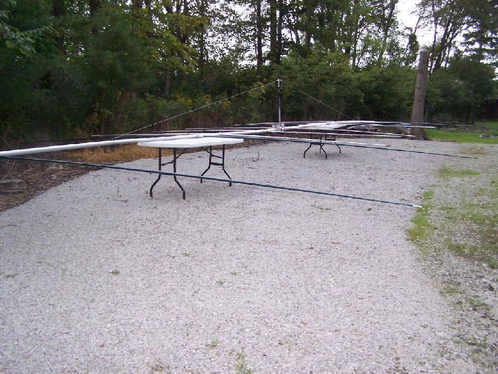
The next pictures are of the new Horizontal Waller Flag antenna on the ground.
This the assembled horizontal waller flag plus the 5 10M HyGain elements. Ready to go up!
The boom is 44 feet long. The dual loops are 26 feet across and 14 feet lengthwise to the boom.
Internally what you don't see inside the boom are two matching transformers to the two loops plus two resistors one for each loop.
In the middle you find an additional match to your 50 ohm coax transformer and the phasing connections.
This one several of the guys carrying the 75 pound total weight antenna out to the front yard in preparation to
take it up onto the tower.
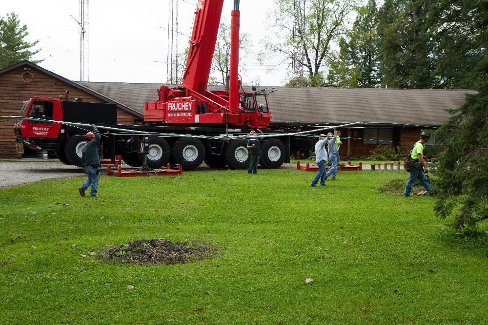
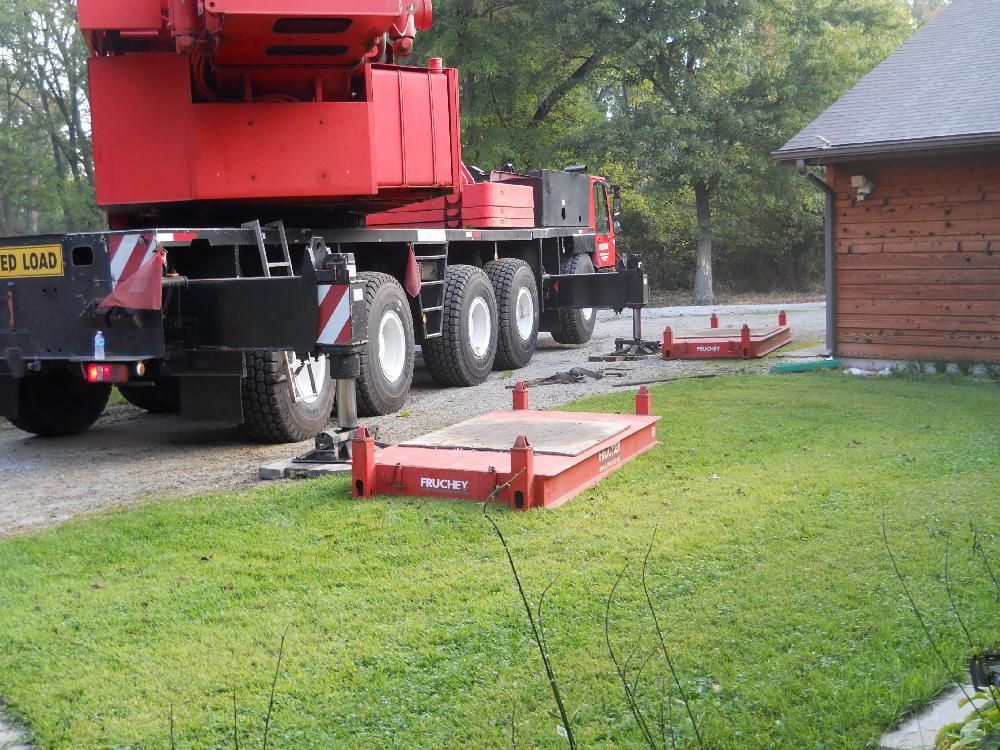
Next some pictures of the Crane being setup for the project.
Adding the additional Weights for the crane Total of 66,000 pounds worth of added weight needed for this job. Plus whatever the crane weighs.
I will give you a little hint. First notice the 5 axles on the crane. They all five Steer when the crane is moving about. The Crane operator said that each axle is set to maintain 21,000 pounds when this crane is going down the road. x 4 or maybe times 5?
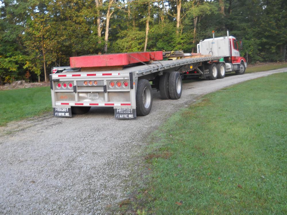
And out in the street yet the Semi with the added 59 foot boom.
Crane is planting the pads to spread the load that is about to be added to the crane.
Adding the Additional 59 foot boom
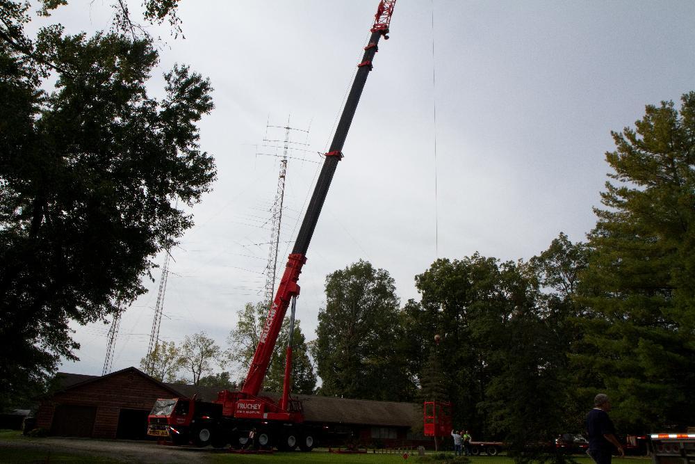
Crane up with the ManCage Ready to go
The first trip up was to remove the old 10M yagi. That is the second one from the top in the above picture. See Video for the removal of the old antenna.
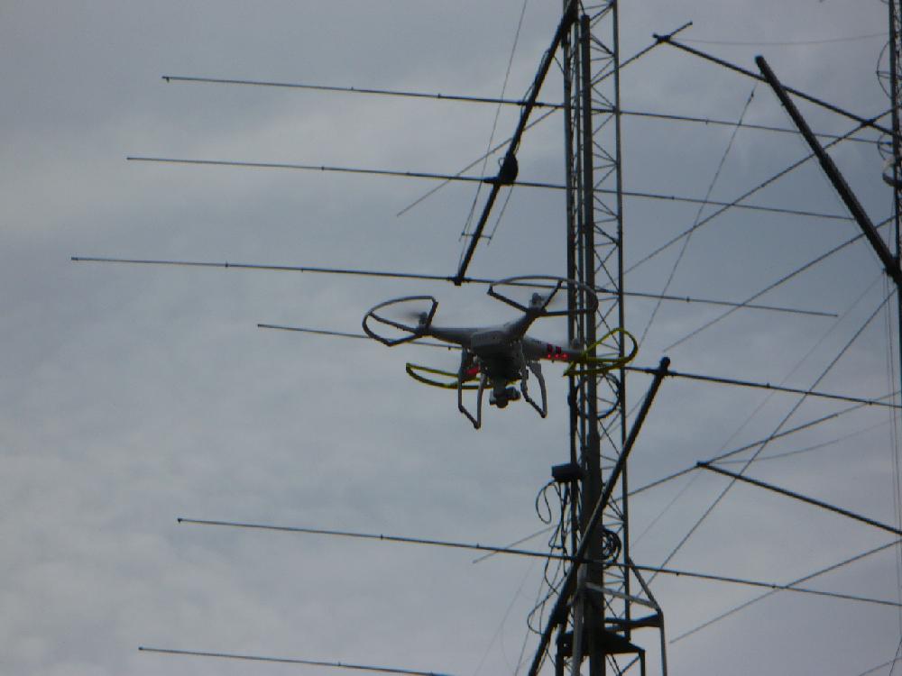
Next was to bring in the new antenna and up it goes.
Notice the QuadCopter in this picture. See the Video taken by the Drone on YouTube
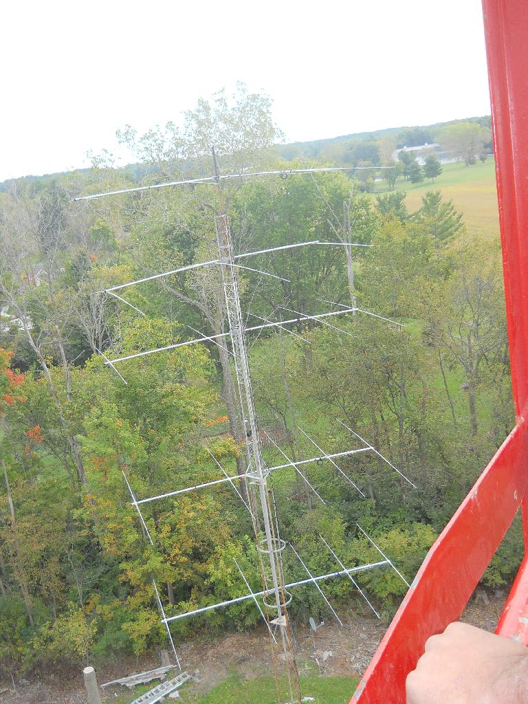
Below picture is a nice view of the smallest of the three towers while we are on the way up with the new antenna.
This tower is a 4hi stack of 5 element HyGain 10M yagi's with an additional 3 element 20M yagi between the top pair of 10M antennas.
The whole works turns with a single rotor from the bottom. The upper portion is Rohn35 tower. That isn't a typo it is 35 Rohn slightly better 25G
The fixed tower is the bottom 50 feet of what used to be a Pirod 100 foot tower
The lower antenna is hanging on the cage affair down from the rotary upper Rohn tower.
Yes that is one very large section of pipe in the middle holding the whole works together. The top antenna is at 88 feet.
The Rotor is 3 feet above ground level. If I take the chain off the mast sprocket you can turn that whole stack with one hand by grabbing
and twisting the 2 inch at the bottom mast pipe. Yes I designed and built this one. It was put up in 1990
The Rotor is a 1/3HP 120Vac standard motor driving two tandem worm gear boxes. From there a chain drive with #100 chain the mast pipe.
Direction information is collected by a 500 ohm wire wound pot on the bottom end of the mast and the control box in the shack is a slightly modified
HamIV control box. It sends out 24Vac to a 24 volt reversing motor starter. And of course gets it's direction information from
the 500 ohm pot on the mast. Cogged Rubber belt drive ratio of 1 turn of the mast equal 300 degree turn of the pot.
The rotor for the top of the #2 tower is built the same way. Four of the five Rotors in these three towers are at waist height from the ground.
Only the Telrex on the top of the tallest tower is up in the air. It had to come down last year for rebuilding the gear boxes. That was
one real PITA project. The Rotor was at that point 30 years old. Guess one can't complain about having to do some rebuild
work on a 30 year old rotor.
Nice View of the crane below us
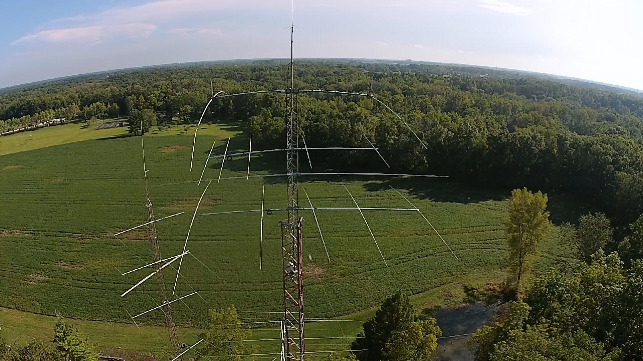
A really nice view of the countryside from about 170 feet above the ground level. No I don't think we can really see that much curvature of
the Earth at this level. Me and Fruchey are moving in to remove the old 10M yagi. First part of the project was to get the feedline off the old 10M yagi as it is
supposed to later be attached to the new 10M yagi.
These guys the Crane op and the man with me in the ManCage are REAL PRO's. Get us in there without damaging any of the elements or
other parts of any of the antennas above or below us. Never any jerking around always nice and smooth and they can move us ONE INCH if that is what
they want to do with that Crane and the Excellent Operator. Did you notice in the one picture the operator had his hand up in front of his face?
He wasn't saluting us. He was shielding his eyes from the sun due to the time of day and being a very nice warm sunny day it was.
So he is not only watching he is taking his directions from the guy in the mancage with me. Amazing pair they are.
Off the the lower left you can see tower #2. After we replaced this 10M antenna with the new antenna we replaced some 1/2 elements on a 20M yagi at 100' level
and back on the small tower another partial element had come off of it and was replaced. Original HiGain Element Clamps are Lousy. They sometimes fall apart
after 20 years or so. Replaced with stainless steel hose clamps and a drilled hole with a nice big pop-rivet into the joint.
I bet they don't come apart again!
Thanks again to the wonderful people from Fruchey Inc and to many of my friends who assisted in many ways with this project.
The Horizontal Waller Flag antenna is finally UP and on the tower and it works very well. More later as we get additional pattern information
and see just how well it does work.
73 for now
John k9uwa
UpDate August 2018
The antenna is up and yes it works very well. Last winter season I managed to get
Five New Ones bringing me to a total of 321 and the Need List is shortened to
Only 29 left in the World that I still need on the 160M Amateur Radio Band.
John k9uwa