I built this 5th Zenith Yacht Radio to find out what one of these radios is worth
if it is totally restored plug and play and sold on an open venue such as Ebay.
It took me 5 years to accumulate the needed cabinet speaker and chassis to build this 5th radio
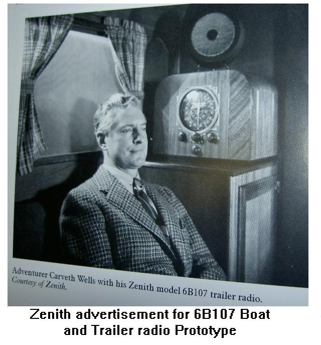
notice that the radio in this first Zenith AD is a model 6V27 which was of course replaced
once the new model year Zenith radios came out with the 6B107 / 6B129
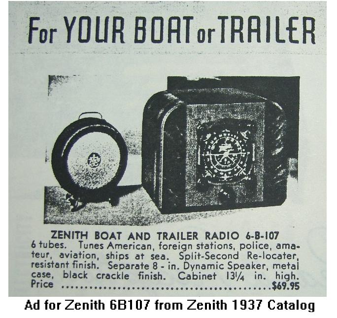
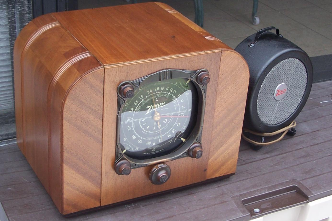
Yes, for your Boat? More like Yacht than Boat consider the size of the radio + speaker and
this was 1937. Also consider the environment that these radios went into. Probably mostly Salt Air.
Estimates are that Zenith build probably less than 1000 of this model. So the survival rate
probably wasn't the best.
It took three chassis plus 1 speaker and 1.5 cabinets to build this 5th Zenith Yacht Radio
Yes even the best of the three chassis required a refinish job.
The Tuner spent time in our ultrasonic cleaner as did many other parts.
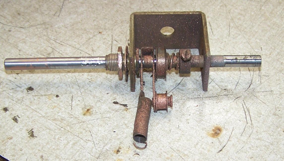
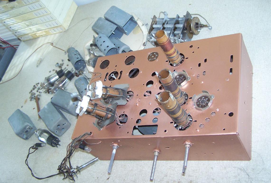
Yes take it all apart to remove the rust.
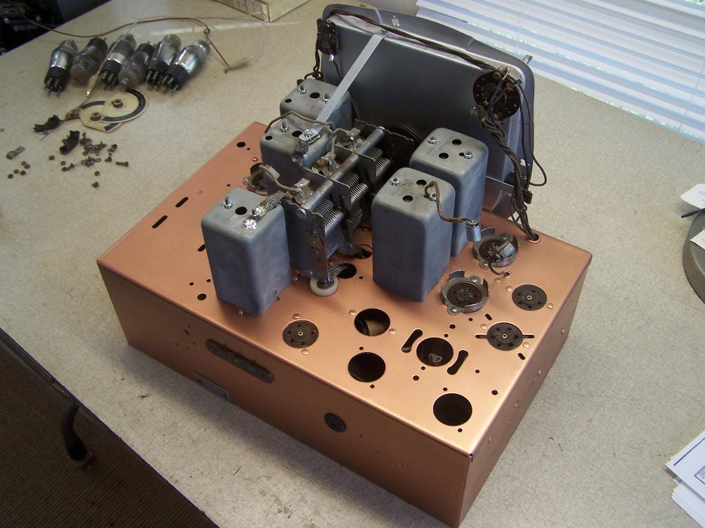
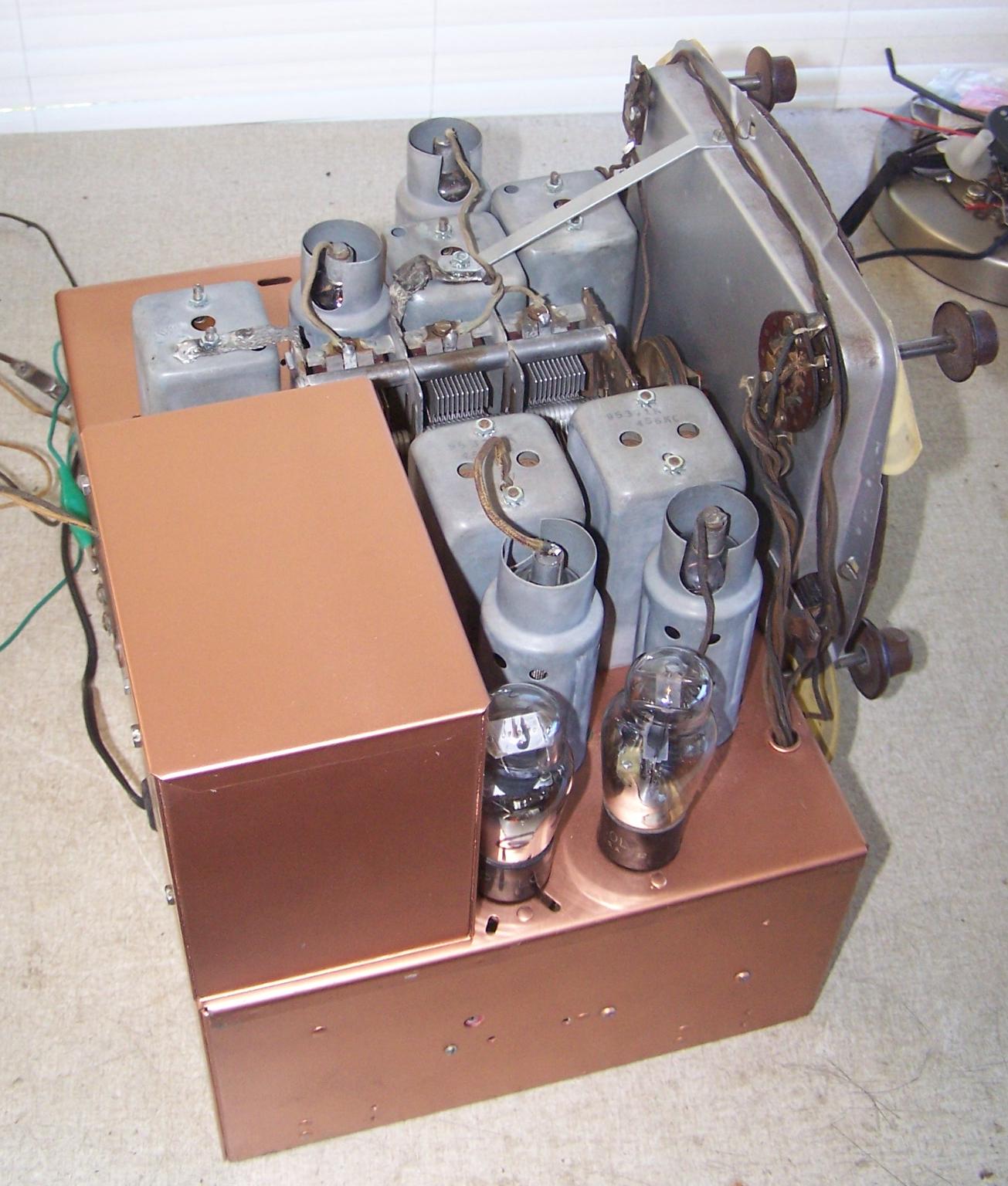
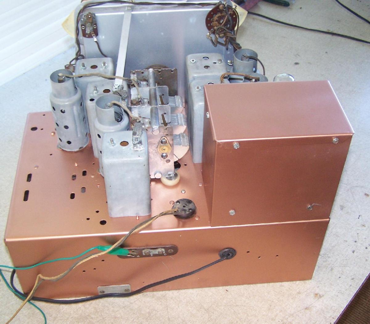
Start putting the radio back together
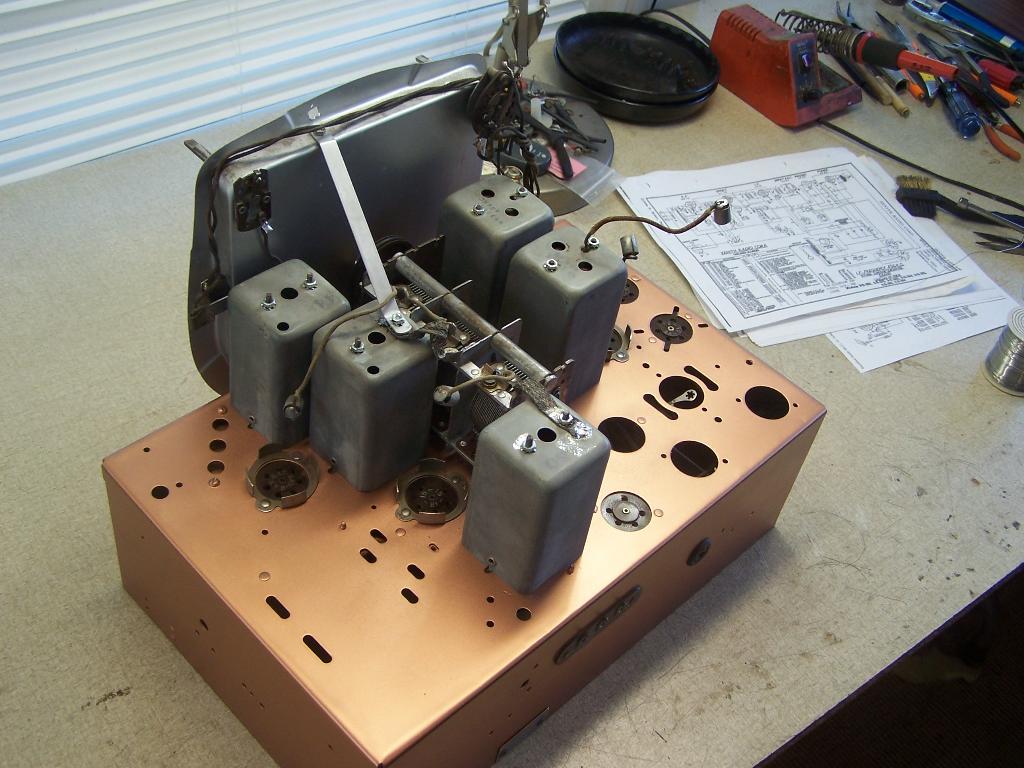
Yes lots of rewire and redesign on this Zenith Yacht Radio
Original Tube Lineup 15 6a7 15 75 76 19 plus synchronous vibrator power supply
The original 6B107 was powered from a 6 volt battery.
New Tube Lineup 39 6a7 39 75 76 41 + totally replace the 6V power supply with a 120vac supply
A type 39 tube is nearly the same as a type 15 except it is 6.3vac rather than 2vdc filament. The type 19 audio tube is also a 2 volt
battery type tube so it needs to be replaced. It is a 6 pin tube socket so a type 41 was selected to replace this tube. I would have
used a type 42 except the glass envelope is larger and it would be touching the large metal box that houses the power supply.
So the first step is to rewire all filaments for 6.3vac. Remove wiring from On/Off switch as it will be in the 120vac and no longer in
the 6volt wiring. Next is a total redesign of the final audio stage. Strip out all the wiring for the 19 tube. Redesign an audio
stage for a type 41 tube and build it.
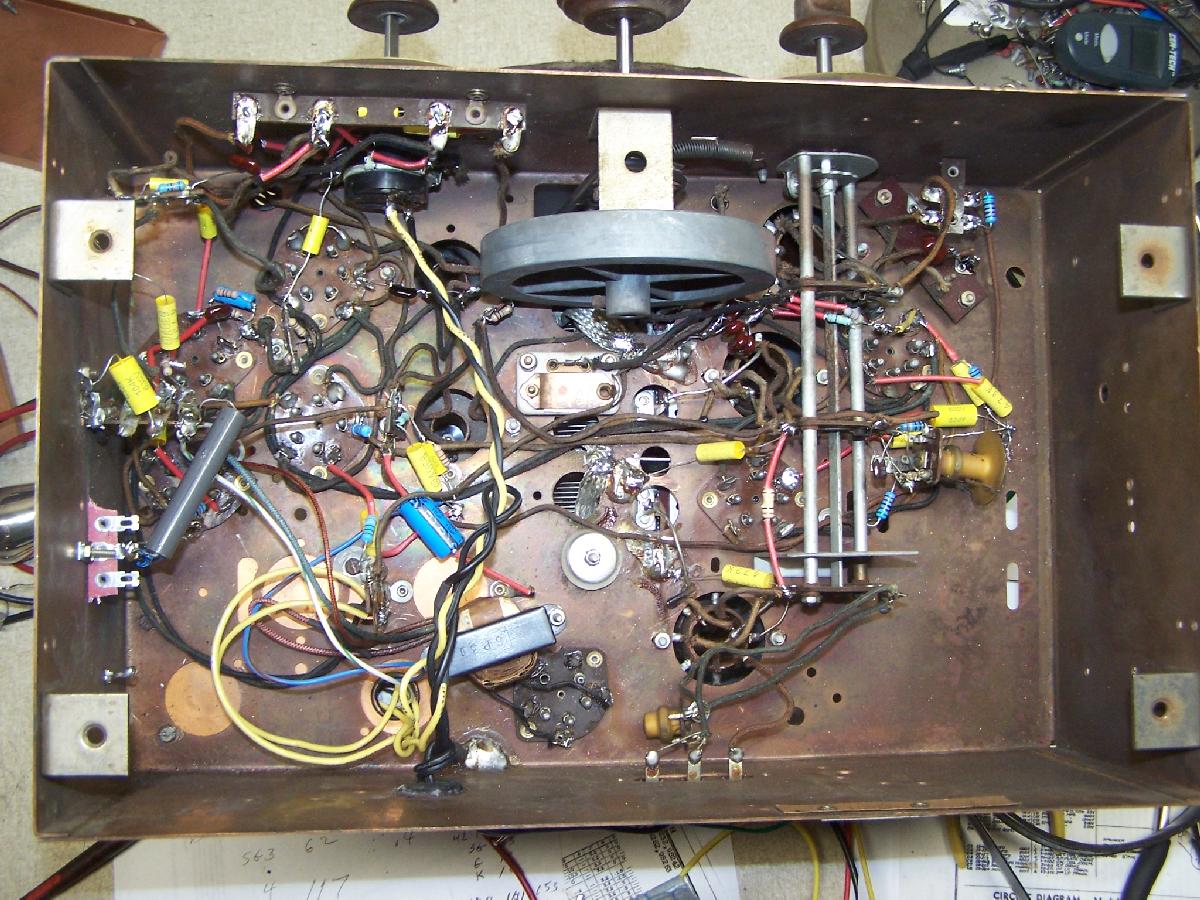
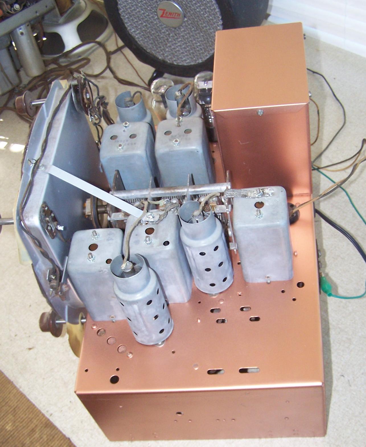
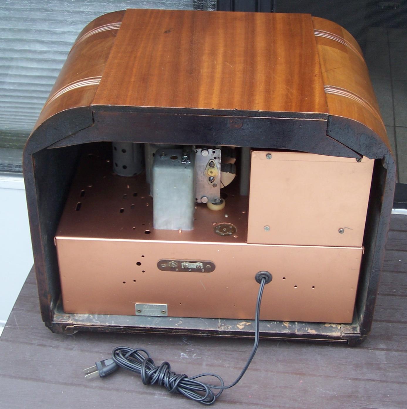
What you don't see is inside that large metal box. It contains the 120vac power supply. You need at least 2.4 amps @6.3v so
call it 3 amps plus something around 250 volts DC for your B+ supply and various lesser voltages for screen supplies etc. So inside
that box you will find a power transformer plus a couple 1N4007 diodes a couple electrolytic capacitors and an iron core choke.
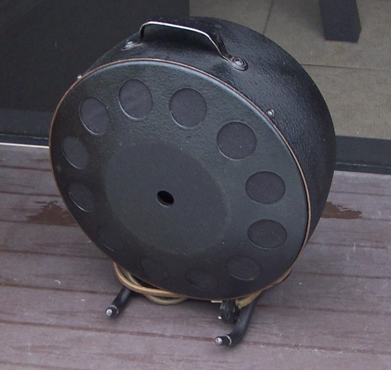
No field coils in these external speakers. Plus a large string of power resistors to supply the various lower voltages
needed for other parts of the circuitry. The idea being that from the topside this radio looks no different than it did when
it was 6Volt battery powered. All mods are under the chassis or inside that power supply box. Since this was my 5th Boat
radio to modify I had learned a few things from the previous four radios. The type 76 tube stage could have been left out as the
triode portion of the 75 tube is adequate to drive a type 41 / 42 / 6F6 / 6K6 / 6V6 pentode tube. But, since it was already
there I might as well leave it alone and just depower it so it doesn't over drive the type 41 tube. Also some reduction to
the triode portion of the 75 tube from what you would normally find in AC powered radios that used a type 75 tube.
The radio is very sensitive with the type 39 tuned RF stage ahead of the oscillator/mixer 6A7. The AVC circuit works well so
you don't end up with over driving stages of the radio. You might notice the batch of Mica Capacitors just a bit behind the
flywheel weight on the dial drive. Those provide the padder capacitors for each of the two shortwave bands. Zenith used
yes a real trimmer capacitor to adjust the 600 khz broadcast band padder but for each of the two short wave bands they
used a fixed mica capacitor. If you really want accurate tracking from top to bottom of your short wave bands then you have
to find the right combination of Top end of band Oscillator Trimmer setting plus Bottom end of the band Padder capacitors. To
complicate things more so Zenith in the large chassis 1937 radios 6V 6S 8S 10S chassis used the trimmers on top of the
"Gang" or Tuning Capacitor whichever you choose to call it. The Three section Cheese slicer on top of the chassis.
They chose to use the three trimmer on top of the tuner to first be set on the "B" band at 6 Mhz. And then they used a
separate trimmer to set the 1500 khz BC band and 18 mhz near the top of the "C" band to set the oscillator frequency.
Then the Detector and Antenna sections were first peaked at 6 MHZ and then slight adjustment band at 1500 khz
for the BC Band and ended up with small trimmers for the Det behind the tuner. And of course these "Fixed Padder"
Mica caps for the bottom of both SW bands. So all of these adjustments will interact with each other. I used a fixed mica cap
and added temporarily a trimmer capacitor for padders on each of the Short Wave bands until I arrived at the final settings that
gave me accurate trackingand reasonably even gain across all three bands. Then measured the temporary padder trimmers
and put in the final fixed mica caps.
Now on with the rest of the pictures as this highly modified Zenith Yacht Radio gets reassembled.
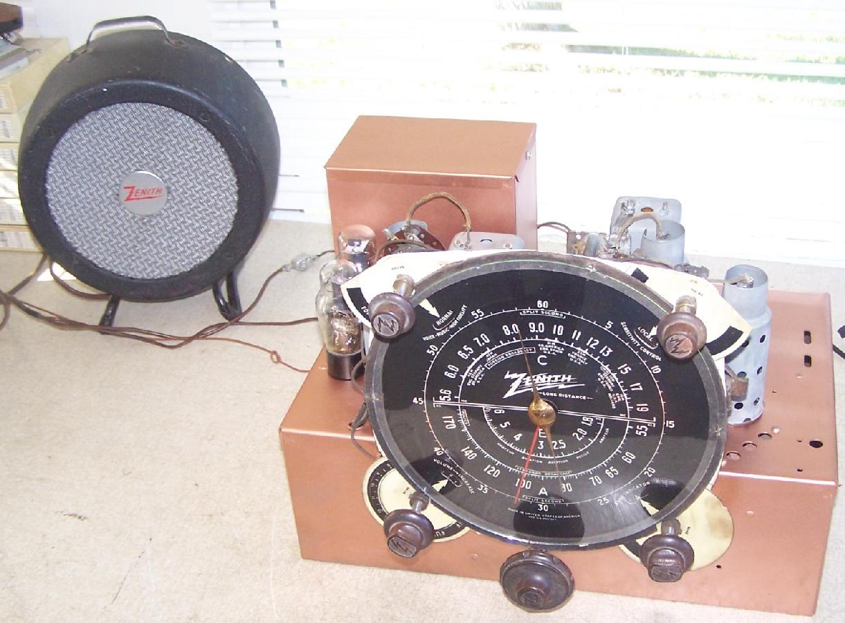
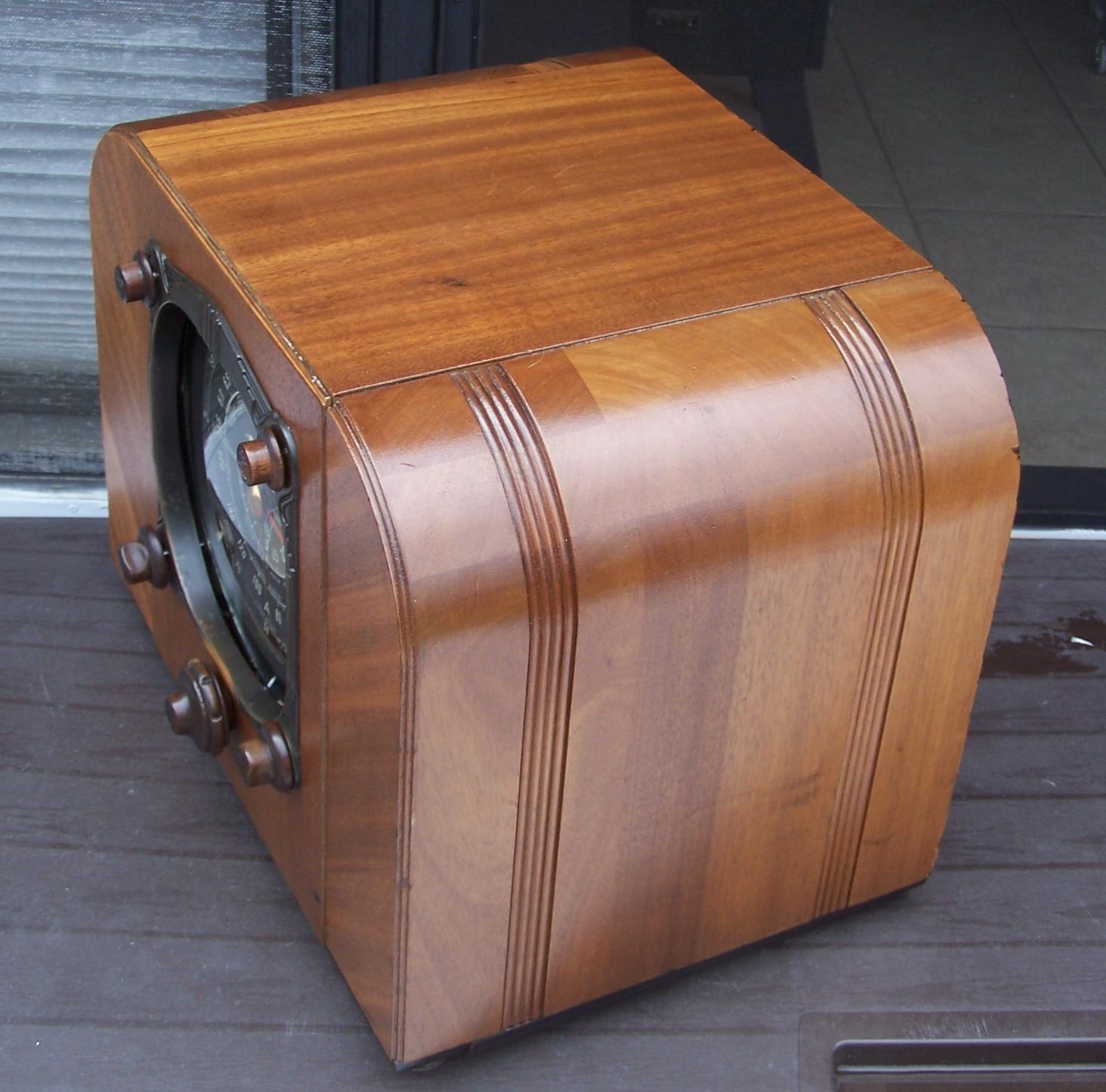
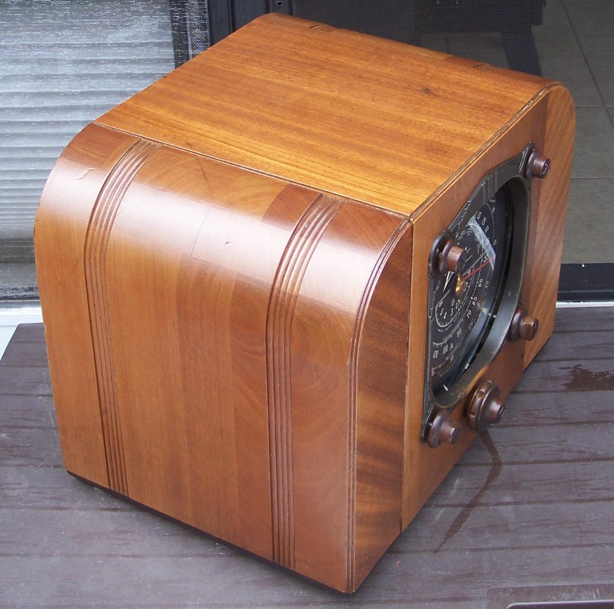
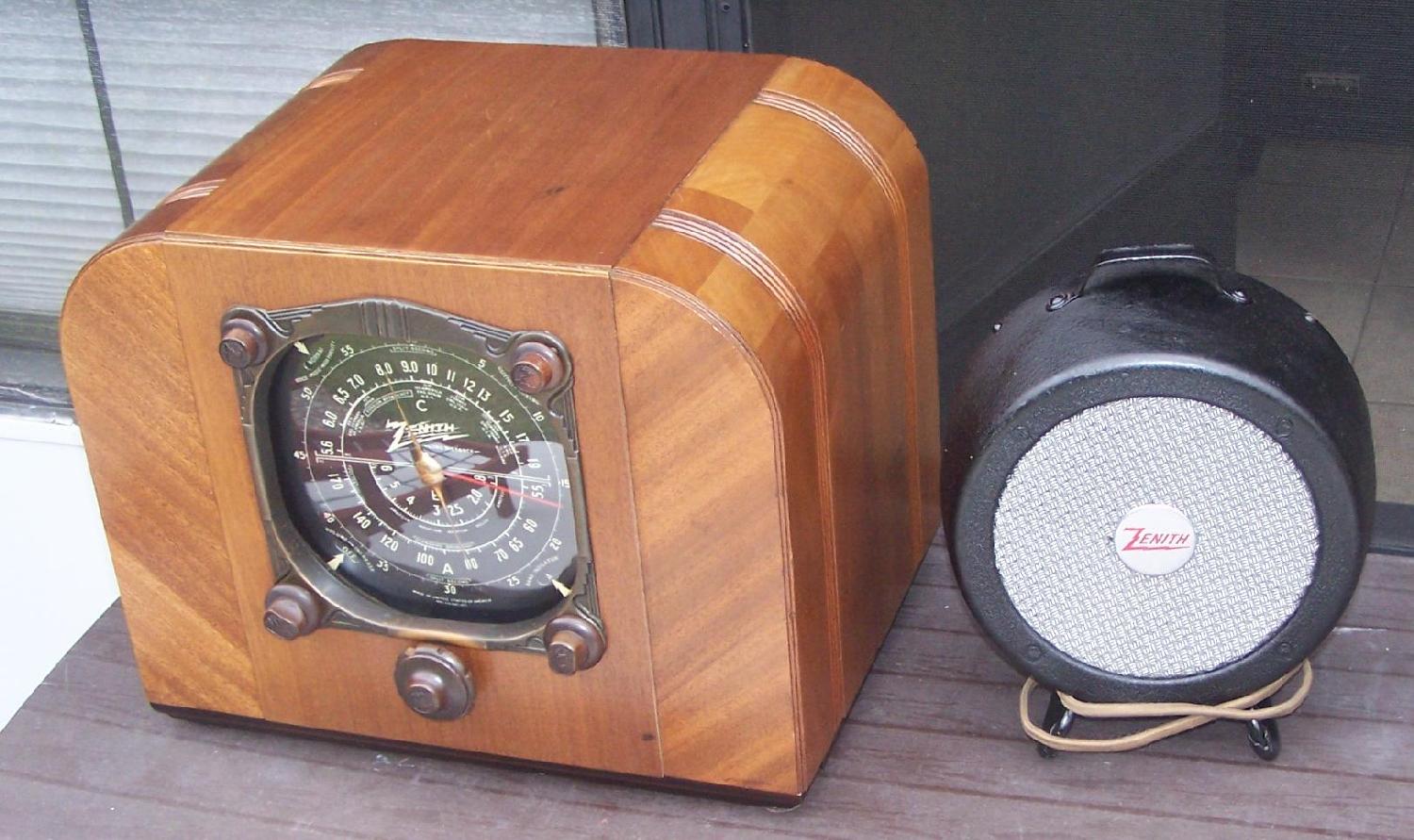
So above is the 5th Zenith Yacht radio that I have modified for use on 120v AC rather than 6vdc.
Some will say I never should have modified any of these radios. They should have been left alone as 6 volt DC battery
powered radios. To those I will say I think that my modified nice looking complete operational radios have a better
chance of surviving another 80 years than if they had been left alone as rusty, broken cabinets and speaker missing
radios they would have soon ended up in a dumpster.
As to the other question we will never know the answer to that one. Only that this radio sold for 2K.
FleaBay killed my auction less than a day before it was due to end.
Back to the Home Page JohnJeanAntiqueRadio.com